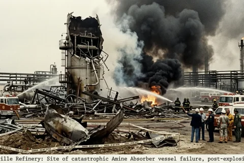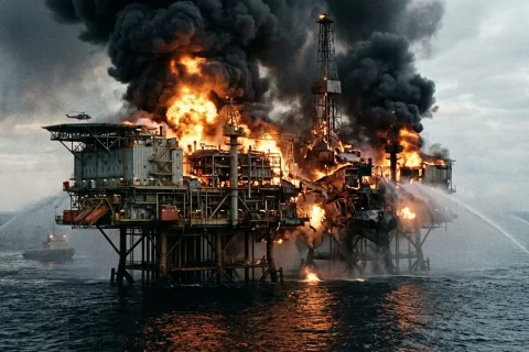
On January 4, 1966, the Feyzin Refinery near Lyon, France one of history’s most significant industrial accidents occur. A routine maintenance task escalated into a catastrophic fire and a series of devastating Boiling Liquid Expanding Vapour Explosions (BLEVE). Claiming 18 lives and injuring 84 others, this disaster fundamentally reshaped modern safety regulations and remains a definitive case study in the risks of pressurized gas storage.
Incident Description
An operator was draining water from a propane storage sphere via a DN 50 (2″ NS) vertical drain leg below the sphere. The drain had 2 manual isolation valves in series. Both were opened but, contrary to operating procedure, the lower valve was half-opened first, then the upper valve was opened further.
When draining was almost complete, the upper valve was closed, then cracked open again. No flow was observed so the upper valve was opened fully. A blockage (probably ice or hydrate) suddenly cleared, and propane gushed out. The handle of upper valve fell off and could not be reinstated.
Attempts to close the lower valve failed as it had frozen in the half-open position. A large vapour cloud formed and drifted to a nearby road where it ignited and flashed back to the sphere causing a fierce fire. Around 1 hour later, a boiling liquid expanding vapour explosion (BLEVE) occurred as the sphere ruptured.
Some shrapnel struck the support legs of an adjacent sphere which then collapsed and toppled over. Damaged pipe fittings on the toppled sphere began discharging liquid which further fed the fire and, 45 minutes later, this second sphere ruptured in another BLEVE. Three more spheres collapsed and ruptured but did not explode.
System Components & Description
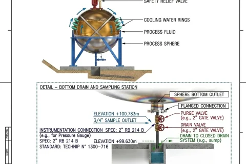
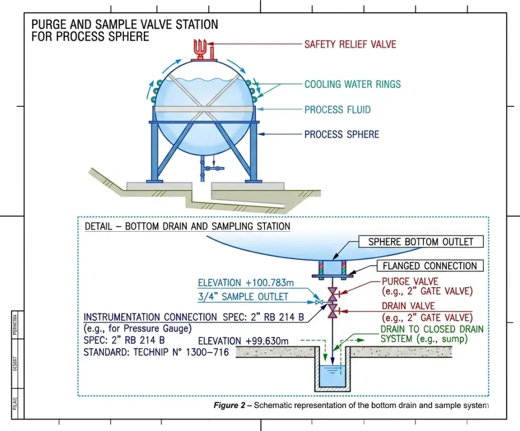
The diagram illustrates the bottom drainage configuration of the 1,200 m³ propane sphere (T 443), which was the primary point of failure.
| Feature | Description |
| Propane Sphere | A pressurized storage vessel (1,200 m³) used to hold liquid propane. |
| Cooling Rings | External piping designed to spray water on the sphere’s surface for cooling during a fire. |
| Upper Valve (Isolation) | A 50 mm (2″) manual gate valve located closest to the hull. Its role was primary isolation. |
| Lower Valve (Throttling) | A second 50 mm manual valve used to control (throttle) the flow of water and impurities out of the tank. |
| Drain Sump | The open collection point where drained liquids were discharged. |
Basic Cause
Basic cause of first fire was ignition of a vapour cloud formed by accidental release of a large quantity of propane from an open drain. Basic cause of first BLEVE was fire engulfment and overheating of the sphere.
Critical Factors of the Incident
- The lower drain valve was erroneously opened before the upper drain valve (causing Joule-Thomson chilling and ice or hydrate formation)
- The ground under the sphere was level (allowing pooling of leaked propane in the bund).
- The firewater pump capacity was insufficient to protect all the spheres.
- The local fire brigade did not try to cool the burning sphere, mistakenly believing it would be protected by its PSV (they directed their hoses to cool 4 adjacent spheres instead).
Root Causes
- Failure to follow operating procedure (drain valve operating sequence)
- Inadequate storage sphere design (support legs not reinforced)
- Inadequate drain system design (removable valve handles, open discharge in close proximity to valves)
- Inadequate overpressure protection (absence of remote depressuring valve)
- Insufficient active (water spray) and passive (insulation) fire protection
- Failure to train local fire brigade on how to deal with this type of incident.
Lessons Learned
- Sphere support legs should be reinforced (for shrapnel impact protection)
- Storage spheres and support legs should be insulated (for fire protection)
- The ground below spheres should slope towards a collection pit outside the sphere shadow (to avoid pooling under the sphere)
- A deluge system capable of flooding the outer surface of the sphere should be provided (and
regularly tested) - The drain system should include a remote-operated, accessible, fire-safe, quick shut-off valve (min. distance from the sphere), a throttle valve at least 1 m (3 ft) further downstream and a drain pot connected to a closed drain. The line should have welded joints (where practicable) and should be self-draining (no pockets) and well-braced (to minimise vibration). Screwed fittings should be prohibited (except for instruments)
- Flammable gas detectors alarming to DCS should be provided (for early leak detection).
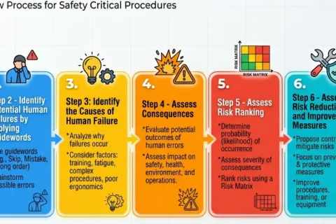
Key Takeaways for HAZOP Studies
The Feyzin Refinery disaster provides several valuable lessons for HAZOP teams:
- Consider small leaks as major hazards – Even a minor LPG leak can escalate rapidly if not detected and controlled promptly.
- Evaluate isolation and draining procedures – Incorrect valve operations or delayed isolation can significantly worsen an incident.
- Assess fire and explosion escalation scenarios – Initial fires can lead to vessel overheating, BLEVEs, and widespread damage.
- Review emergency response actions – Operator and emergency responder actions during an incident can influence the severity of the consequences.
- Analyze equipment exposure to external fire – Storage vessels and process equipment exposed to fire should be evaluated for thermal radiation and overpressure effects.
- Verify the adequacy of safeguards – Gas detection systems, emergency shutdown systems, pressure relief devices, and fire protection measures should be assessed for effectiveness.
HAZOP Lesson: The Feyzin disaster demonstrates how a routine operational issue can escalate into a catastrophic event when a hydrocarbon release, delayed isolation, and fire exposure occur simultaneously. HAZOP teams should pay particular attention to leak scenarios, emergency isolation, and fire escalation effects when evaluating LPG and hydrocarbon systems.
Top References
- Learning Lessons from Major Accidents by IChemE
- https://www.aria.developpement-durable.gouv.fr

Certified Functional Safety Professional (FSP, TÜV SÜD Germany), Certified HAZOP & PHA Facilitator, LOPA Practitioner, QRA/FERA and Specialist in SIL Verification & Functional Safety Lifecycle, with 18 years of professional experience in Plant Process Safety across Petroleum Refining and Fertilizer Complexes.