Fluid Catalytic Cracking (FCC) is the conversion process used in a petroleum oil refinery to convert the low-value heavier long-chain hydrocarbon refinery fractions such as heavy vacuum gas oils into greater economic value lighter products, mainly gasoline, distillate, and LPG. The rapid cracking reactions of the FCC unit depend upon the circulating or fluidization of a powder zeolite catalyst with the liquid feed into a riser of the FCC reactor for a few seconds. This unit is normally, installed to produce more gasoline.
The FCC unit is particularly applied to maximize gasoline production in oil refineries over residual fuel oil. The FCC yields a high volume of gasoline of good quality with high octane and low RVP. However, the volume yield of diesel is low with inferior quality, since it is made up of cracked material which tends to have low cetane. The FCC is generally less valuable than a hydrocracking unit, in a market where diesel is preferred over gasoline.
Applications of Fluid Catalytic Cracking Unit
The FCC unit can process various refinery streams with the boiling range 315~575 oC, including; atmospheric gas oils, vacuum gas oils, coker gas oils, thermally cracked gas oils, vis-breaking distillates, solvent de-asphalted oil, lube extracts, and hydrocracker bottoms. Further, Hydrotreated vacuum gas oil and desulfurized atmospheric residue feeds can also be processed in the FCC unit, in that case, it is called Residue Fluid Catalytic cracking (RFCC).
Typical FCC Products
Typical FCC unit products are as follows:
- Fuel gas (ethane and lighter hydrocarbons)

Typical FCC Products Yield Wt % Range - C3 and C4 liquefied petroleum gas (LPG)
- Gasoline
- Light cycle oil (LCO)
- Heavy Cycle Oil (HCO)
- Fractionator bottom (slurry oil) Although gasoline is typically the most desired product from an FCCU or RFCCU, design, and operating variables can be adjusted to achieve other products. Depending upon the unit design the FCC products can be further treated before being blended with other refinery streams.
Pretreatment of FCC Feed
There are various amounts of contaminants present in the FCC feed such as sulfur, nitrogen, conradson carbon residue (CCR), and metals, particularly in high boiling fractions. These impurities have negative effects on the unit performance. Hydrotreating significantly improves the properties of the FCC feeds through Hydrodesulfurization, Hydrodenitrogenation, Hydrodemetallization, Aromatic saturation, and conradson carbon removal.
- FCC products, rich in sulfur will require, specialized processes for their treatment to produce low sulfur products. Further, sulfur in feed ends up in coke on the catalyst. SOx is formed when the catalyst is burned away.
- Nitrogen being basic in nature tends to poison the catalyst by neutralizing its acid sites and acts as a temporary poison. To compensate for nitrogen poisoning reactor temperatures have to increase. Further, the remaining nitrogen ends up as coke on the catalyst that is converted to NOx and leaves with flue gases.
- Metals such as Vanadium, Nickel, and Sodium present in the FCC feed, permanently poison the catalyst and lower its activity. Further, these metals proceed with side reactions, thus hindering the normal cracking reactions.
- Heavy feeds typically have high carbon residues that deposit on the catalyst with the normal coke and results in higher overall coke on the catalyst. Burning this coke requires additional regeneration air and higher temperatures which may limit the capacity of the unit.
- The saturation of aromatics in the feed provided the biggest benefit because it converts hard to crack aromatics easier to crack naphthenes.
Table shows the change in properties after the hydrotreatment of the FCC feed.

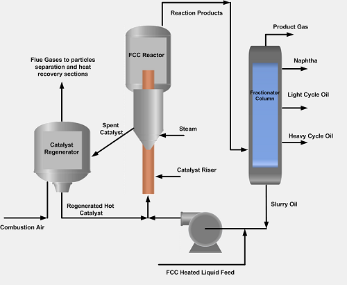
Fluid Catalytic Cracking Unit Process Description
The process flow diagram of the Fluid Catalytic unit is shown in Fig below. The VGO feed heated up to 315~425 oC and mixed with the hot regenerated catalyst (640~760 oC) at the bottom of the riser, which is a long vertical pipe. The liquid feed is vaporized due to a hot catalyst and goes up in the riser for a short period of 2~10 seconds.
The temperature at the riser outlet is a key factor in determining conversion and product quality. At the top of the riser, the temperature reaches nearly 550 oC. The riser is the main reactor in which the endothermic reactions take place. High temperature favors the production of olefin-rich light gases at the expense of gasoline, moderate temperature favors the production of gasoline, and lower temperature increases the distillate yields.
From the top of the riser, the gaseous products flow into the fractionator column, while the separated catalyst and some heavy liquid hydrocarbons flow back into the disengaging zone of the FCC reactor. Steam is also injected into the stripper section to remove the oil from the spent catalyst. The oil is stripped from the catalyst and moves along with rising vapors to the fractionator. The spent catalyst is sent to the regenerator at a temperature of 475–550 oC.
The coke on the spent catalyst, produced in the FCC cracking reactions, is burned off in the regenerator by introducing air. Excess air is utilized to ensure the efficient combustion of coke. The produced hot flue gases exit at the top of the regenerator that contains carbon dioxide, carbon monoxide, water, and excess air at the regenerator temperature. The flue gases can also be sent to the power recovery unit to produce superheated steam.
The FCC unit operation remains at a steady state as long as a heat balance exists between the heat produced in the regenerator and the heat consumed in the reactor. In both the reactor and the regenerator, hydro cyclones are installed to remove any solid catalyst particles carried out in the overheated gaseous stream.
FCC Unit Chemical Reactions
The VGO undergoes the desired ‘primary cracking’ into gasoline and LCO. A secondary reaction also occurs, which must be limited, such as a hydrogen transfer reaction which lowers the gasoline yield and causes the cycloaddition reaction. The latter could lead to coke formation needed to provide heat for catalyst regeneration.
FCC Unit Catalysts
There are three types of commercial FCC cracking catalysts, 1. acid-treated natural aluminosilicates, 2. amorphous synthetic silica-alumina combinations, and 3. crystalline synthetic silica-alumina catalysts called zeolites or molecular. Zeolite types catalysts are preferred over other types due to higher activity, higher gasoline yields, production of gasoline containing a larger percentage of paraffinic and aromatic hydrocarbons, lower coke yield, increased isobutane production, and ability to go to higher conversion, high hydrogen transfer, hence saturation of products takes place at the primary steps of cracking.
Modes of Operation of FCC Unit
FCC unit can be operated at different operation modes as per operational requirements. Maximum Gasoline mode is characterized by the use of an intermediate cracking temperature (510 to 540°C), high catalyst activity, and a high catalyst/oil ratio.
Maximum Middle Distillate mode of operation is a low-cracking-severity operation in which the first pass conversion is held to a low level to restrict re-cracking of light cycle oil formed during initial cracking. The severity is lowered by reducing the riser outlet temperature (below 510°C) and by reducing the catalyst/oil ratio.
Maximum Light Olefin Yield: The yields of propylene and butylenes may be increased above that of the maximum gasoline operation by increasing the riser temperature above 540°C and by use of ZSM-5 containing catalyst additives.
Most of the existing FCC units have been designed or modified by six major technology licensors:
1. UOP (Universal Oil Products)
2. Kellogg Brown & Root—KBR (formerly The M.W. Kellogg Company)
3. ExxonMobil Research and Engineering (EMRE)
4. The Shaw Group Inc.
5. CB&I Lummus
6. Shell Global Solutions International 7. Axens & 8. Foster Wheeler – FCC technology
For further information, discussion and queries please comment in the box below or contact at admin@ or follow us on Facebook & LinkedIn.

Certified Functional Safety Professional (FSP, TÜV SÜD Germany), Certified HAZOP & PHA Facilitator, LOPA Practitioner, QRA/FERA and Specialist in SIL Verification & Functional Safety Lifecycle, with 18 years of professional experience in Plant Process Safety across Petroleum Refining and Fertilizer Complexes.