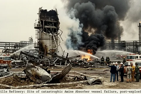
Amine systems are used to remove CO2/H2S acid gases from process gas streams in the refinery, petrochemical, and natural gas industries. Foaming is defined as the dispersion of gas bubbles in an amine solution i.e. the gas becomes entrained with the amine liquid and is probably the most common operating problem that increases operating costs and reduces the treating efficiency. Plant upsets due to foaming in Amine treating units require an immediate response. Amine solution turns into foam in an amine scrubber because the normal froth is stabilized into foam due to the presence of contaminants.
How Does the Amine Convert into Foam?
During normal operation, froth (i.e. small bubbles) is produced as the gas pass through the amine solution on the absorber trays in an amine scrubber. As the bubbles spill over the tray weir into the downcomer, the froth breaks, gas disengages, and the free liquid move downwards. But, when the surfactants present at the gas-liquid interface are adsorbed to the gas bubbles, the bubbles fail to disengage. As a result, the froth height and break time increase, and liquid entrainment in the gas increases. At this point, the bubbles rapidly start converting into foam and move to the upper trays. The liquid level in the column drops while differential pressure across the column goes up.

The contaminants or surfactants preset at the gas-liquid interface change the surface properties of the amine solution. Surfactants reduce the surface tension and increase the elasticity/viscosity of the amine solution, thereby promoting and stabilizing foam in the amine system as compared to the fresh uncontaminated amine. High surface tension and low viscosity of the amine help to break the bubbles within seconds during normal operation. Further, lower amine solution temperatures (sensible heat) and high concentration favor increased viscosity, therefore foam stability.
Effects of Foaming on Amine System or Consequences of Foaming in Amine System
- Excessive amine solution losses due to amine carry over to the downstream section.
- Level rise of suction knock out vessel of recycle gas compressor in hydroprocessing units, that may lead to the shutdown of the compressor.
- Corrosion and upset in the fuel gas system of the refinery due to H2S slippage.
- Reduction in absorption capacity of amine and failure to meet product gas specification.
- Instability and loss in levels of the Amine column.

Amine Scrubber - The color of the Sulphur will become dark if amine is carried over to Claus Sulphur Recovery Unit.
Symptoms of Foaming in Amine Systems
- Sudden rise in differential pressure across the amine scrubber or amine regenerator column.
- Decreasing or fluctuating liquid levels in the amine column.
- Level appearance in the downstream knock-out vessel due to amine carryover.
- Off specification or purity decline of the product gas.
Causes and Control of Foaming in Amine Scrubber
The key to keep away from foaming in the amine system is “to save the amine from being contaminated”. The amine foaming in the absorber column can be avoided by maintaining good quality, concentration in the proper range, and applying a good filtration system so that the amine solution is always free from particulates. Causes of foaming include;
- Condensation of Hydrocarbons in Amine
- Lubricating oil drops coming with the feed gas
- Excessive chemicals injection like corrosion inhibitors, antifoams, etc.
- Suspended finally divided particles like rust, corrosion products, scales, and carbon particles from carbon filter.
- Thermal/Chemical degradation products and heat stable salts.
- Contamination with greases, oils, detergents, and welding fluxes during overhauling and maintenance.
When the foaming symptoms appear, immediately anti foam is injected into the system, to avoid adverse conditions of foaming. After this action, find and correct the root cause of the foaming.
Following are some causes and controls of foaming in the amine scrubbing system;
1.0 Condensation of Hydrocarbons in amine is probably the most frequent cause of the foaming in amine systems. Normally, 3~5 °C differential temperature between amine and gas is maintained. Further, if the concentration of hydrocarbons is increased in the feed gas stream then there are more chances of foaming. Moreover, lean amine temperature should be high enough so that the hydrocarbon dew point is not achieved. Lean amine temperature must be 10 °F above the dew point of the sweet gas. Cold amine ~ i.e. 70 °F (21 °C) will itself have a tendency to foam.
- In the hydroprocessing units, during the startup, the temperature of the amine can be very low due to stalled amine circulation, long distances, or cold weather. Soon as the amine absorber is taken into service, sudden foaming can be faced due to the condensation of hydrocarbons. To avoid this if possible start the long circulation of amine, 1~2 hours before the absorber startup and achieve the desired amine temperature.
- In the Hydrocracking unit, when the reactor temperatures are high and there is more cracking and high conversion, then more hydrocarbon components will go to the amine absorber with the recycle gas, which will result in hydrocarbon contamination despite the proper differential temperature being maintained. To control this, optimize the reactor temperature and perform the skimming activity to remove hydrocarbon present in amine.
2. Poor efficiency of liquid hydrocarbon absorbers at the Gas Concentration unit will lead to the passing of hydrocarbons to the amine absorber and hence foaming.
3. Suspended finally divided particulates (e.g., mill scale, FeS corrosion products, rust, carbon particulates from carbon filters) contained in the feed gas or produced within the amine treating unit. These particles are removed through filtration.
4. Materials introduced into the amine circuit during operation and maintenance, such as excessive antifoam agents, corrosion inhibitors, chemicals, and contaminants in make-up water. Analyze the amine and make-up water and avoid the excessive injection of the chemicals.
5. Contamination of the amine unit equipment with greases, oils, detergents, and welding fluxes during overhauling and maintenance. A hot caustic wash (2 to 5 wt% caustic soda) followed by a hot condensate wash before taking into service can remove these impurities and help prevent foaming.
6. Amines can undergo both thermal and chemical degradation and can produce by-products that cause foaming. Thermal degradation can be avoided by maintaining an optimum regenerator bottom temperature and low amine concentrations.
7. Oxygen contamination of the feed gas or amine unit (usually at the amine sump or amine storage tank). The amine and oxygen react to form carboxylic acids and amine heat stable salts. Heat stable salts (HSS) in amine solution do not break up at regenerator conditions. These salts tie up with amine molecules, which then cannot react with acid gas, and can lead to fouling and corrosion. Avoid air ingress in the system by proper sealing of the tanks and by keeping a blanket with fuel gas or nitrogen.
8. Filters are used to prevent the buildup of particulates and hydrocarbon removal. Mechanical filters remove the suspended particulates while activated carbon removes hydrocarbon oils and surfactants. Mechanical filters are installed both upstream and downstream of the carbon filters to remove carbon particulates from the amine supply. Change out the carbon filter when lab analysis shows no improvement in color or oil removal. Filters replacement/cleaning frequency indicates the condition of amine.
9. Lubricating oil drops coming with feed gas can contribute to or cause foaming. Check the function of the inlet oil separator, coalescer, knock-out vessel, or filter provided for feed gas streams contaminated with compressor lubricating oil.
10. New filter elements that have been washed with surfactants or contaminated with oils during manufacture when first placed in service. These elements should be washed with steam or condensate before use.
11. A feed gas water washing when the feed gas stream is severely contaminated with carboxylic acids or water-soluble, surface-active contaminants. It can also remove aerosols and ultra-fine particles.
12. Onsite or offsite amine solution reclaiming to remove heat-stable salts and amine degradation products. Otherwise, these will remain in the system and may cause foaming. No more than 10% of the amine should be tied up as heat-stable salts.
13. Liquid hydrocarbon skimming facilities are provided in the amine absorber, regenerator, amine flash drum, and the amine regenerator overhead accumulator. Sight glasses are provided on the skimming sections where the interface between amine and hydrocarbon can be seen. Whenever, levels in the skimming sections or level glasses appear, and hydrocarbon layer can be seen then skim out the hydrocarbons from the equipment.
For further information, discussion and queries please comment in the box below or contact us at admin@ or follow us on Facebook & LinkedIn.

Certified Functional Safety Professional (FSP, TÜV SÜD Germany), Certified HAZOP & PHA Facilitator, LOPA Practitioner, QRA/FERA and Specialist in SIL Verification & Functional Safety Lifecycle, with 18 years of professional experience in Plant Process Safety across Petroleum Refining and Fertilizer Complexes.