
Hydroprocessing is not only essential to remove the contaminants from petroleum products but also for breaking the heavy hydrocarbons into lighter ones to produce more valuable products. Hydroprocessing reactions are exothermic and are a major concern during the operation of the unit.
The performance of the hydroprocessing reactor depends not only on the catalyst activity but also on the performance of its internals. The functions of high-performance Hydrotreating reactor internals are; proper flow distribution, maximum catalyst utilization, removal of process heat, avoiding hot spot formation, improved cycle length, flexible operating range, desired product quality, the ability to process severe feeds, maintain catalyst activity, avoid channeling in the catalyst, maintain plug flow of reactants, low space occupancy in the reactor, desired hydrotreating reactions, ease of maintenance and low-pressure drop.
The following are the major internals in a typical hydrotreating reactor as shown in fig. 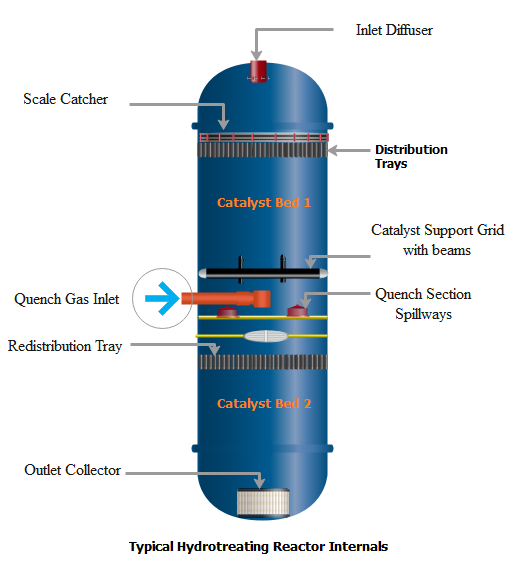
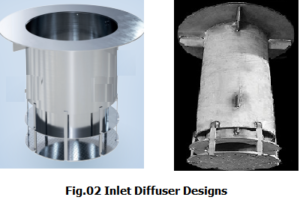
1. Inlet Diffuser
It is installed at the inlet nozzle of the reactor to dissipate the momentum of the combined feed entering the reactor. It creates an even pattern of fluid distribution over the top liquid distribution tray or catalyst bed. Designs vary depending upon the process license. There should be sufficient space between the diffuser and the top tray or the catalyst bed to avoid damage or catalyst fluidization.
2. Distribution Trays
Distribution trays in the hydrotreating reactors are provided at the top of each catalyst bed as a final element of the distribution. In addition, they provide an opportunity for mixing the liquid and vapors. Numerous designs of distribution trays had been developed over the years which include Sieve or perforated trays, Bubble cap trays, Chimney trays, and Vapour Lift Trays (VLT).
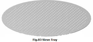
a. Sieve Trays or Perforated Trays
These are simple in design and cheap in construction with multiple holes in them. This type of device is often used for pre-distribution followed by more sophisticated final liquid distribution trays like a chimney, bubble cap, or VLT trays.
b. Chimney Trays
These are multiple small pipes or chimneys that are fabricated on the tray with two or more holes. Liquid from the trays passes through the holes into the chimney which combines with vapors coming from the top and then drops on the catalyst. Their performance is lower at turndown flow rates because it can not maintain the levels over the tray. Its holes can be blocked easily with debris or corrosion particles.
c. Bubble Cap Trays
These are the same as those used in distillation columns but perform different functions. Liquid aspirated with vapors passes upwards through the annular space of the pipe under the cap and then drops on the catalyst bed through the pipe. These are better than Chimney trays because can operate better and maintain the liquid level at low flow rates. It provides better contact between the vapor and liquid as compared to chimney trays.
The main disadvantage of bubble-cap trays is the large size of bubble caps which occupies more space hence fewer numbers of dripping points over the catalyst. Also results in poor distribution near the reactor walls.
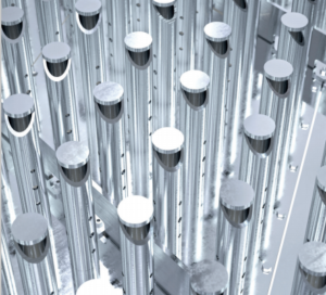
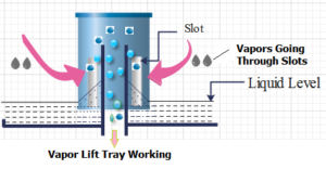
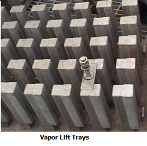
d) Vapour Lift Trays (VLT)
It is the modified design of bubble cap trays. Consists of a cap mounted over a riser pipe fabricated on the tray. The liquid level is maintained over the tray. Vapour passes through the slots or openings lifting the liquid in a co-current fashion. Vapors entrain the liquid and pass through an annular space between the cap and the riser. Advantages of VLT trays are;
- High space density or a high number of distribution points over the catalyst helps in maximum catalyst utilization.
- Cover the reactor walls region.
- Less fouling problems as compared to the chimney trays.
- An out-of-level condition has a very low impact on the operation. It can operate efficiently at low plant loads.
3. Quench Zone
It is designed for multi-bed hydrotreating reactors to inject quench fluid to reduce the equilibrium temperature before the reactants are distributed over the next catalyst bed. It provides the intimate mixing of the cold stream with the hot one and eliminates the temperature wave propagation to avoid hot spot formation in the catalyst bed.
Mostly, unheated Hydrogen gas is utilized as a quench medium which also replenishes the hydrogen gas which has been consumed in the upper bed reactions.
I) The Impingement Plate-type
design is an old one and rotates both fluid streams by 90 degrees in a quench box to ensure mixing. But this design can not ensure temperature control and radial spread at high quench gas rates.
II) Segregated-Phase Mixing design
In this design hot liquid and vapors are separated for single-phase mixing. Separated hot vapors are mixed with cold quench gas and then mixed together with hot liquid. This quench design can work better for low quench gas rate application
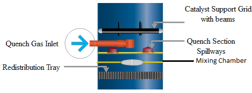
III) Centrifugal or Vortex Type Design
It is widely used in the latest hydrotreating reactors which require less space and can achieve the required thermal equilibrium. It consists of a liquid collection tray, mixing tray (or chamber), perforated distribution tray, and Vapor Lift Distribution Tray.
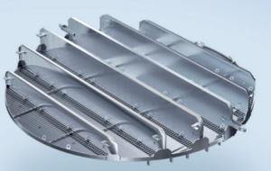
4. Liquid Collection Tray
Liquid and vapors from the top bed through the catalyst support grid drop onto the liquid collection tray. Quench gas is injected by a distributor that provides uniform initial distribution to the gas. The distributed gas and liquid both pass from the liquid collection tray through the openings called spillways over to the mixing tray.
5. Mixing Tray or Mixing Chamber
On this tray, spillways provide the flow path to liquid and vapors from the liquid collection tray in such a way that they move in a swirling or centrifugal motion. Here they make several rotations before being passed through a circular opening in the center. The central opening is equipped with a weir that provides additional residence time for mixing. From the mixing chamber or mixing tray, the process fluid passes through distribution trays before going to the next catalyst bed.
6. Catalyst Support Grid or Beams
It provides support to the catalyst bed and also serves as a screen to avoid catalyst flow along with process fluid. It is located above the quench zone. In addition, distributes the hot fluid above the quench zone.
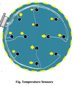
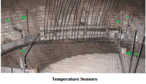
7. Temperature Sensors
These are very critical for performance monitoring and identifying any hot spot in the catalyst bed. Multi-point, temperature sensing devices are provided inside the catalyst bed to monitor the catalyst bed temperature. This arrangement also helps in calculating radial spread temperature.
8. Reactor Outlet Collector
All the reactor effluent is collected and passed through the Outlet Collector. It is surrounded by inert packing to hold the load of the catalyst bed. Its arrangement ensures a smooth flow from the catalyst bed. Moreover, it holds the catalyst volume and saves it to pass through.
9. A scale Catcher
It is provided at the top of the first catalyst bed to entrap the scales and rusts coming with the feed, as a common problem in the hydroprocessing reactor is pressure drop build-up caused by various particles plugging the catalyst bed.
For further information, discussion and queries please comment in the box below or contact admin@, or follow us on Facebook & LinkedIn.

Certified Functional Safety Professional (FSP, TÜV SÜD Germany), Certified HAZOP & PHA Facilitator, LOPA Practitioner, QRA/FERA and Specialist in SIL Verification & Functional Safety Lifecycle, with 18 years of professional experience in Plant Process Safety across Petroleum Refining and Fertilizer Complexes.


15 thoughts on “Hydrotreating Reactor Internals”
Informative Material shared.
Hı faissl.
İ have some questions for the tower design.
Very nice article. Further please initiate discussion and publish more articles related to the catalysts used in different Hydroprocessing operations, performance analysis of catalysts and their selection criteria.
very informative and well explained. Thanks for sharing
Good data regarding trays types but add some shot videos to clear the flow pattern through the reactor each portion
Nice and easy to understand
Share Spillways pictures also