The Safety Instrumented System Safety Lifecycle defines the necessary activities involved in the implementation of SIF occurring during a period of time that starts at the concept phase of a project and finishes when all of the SIFs are no longer available for use. The standards IEC 61511 define and explain all phases of the SIS lifecycle, which should be followed for the reliable operation of the SIS. The SIS safety lifecycle forms the central framework which links together most of the concepts in IEC 61511.
All of the lifecycle phases are mainly grouped into 3 “periods”:
1. Analysis Phase
The SLC (Safety Lifecycle) begins with the initial design of the process conceptually and the definition of the project’s scope. The project scope is defined, and basic engineering is completed to the point where the process risks are sufficiently clear to allow for the definition of a set of Safety Instrumented Functions (SIFs) along with their risk reduction requirements. This segment concludes when the preliminary version of the Safety Requirements Specification (SRS) is ready.
2. SLC Realization Phase or SIS Design Phase
The basic design of the Safety Instrumented System (SIS) is elaborated sufficiently for SIL verification, which confirms that the risk reduction and architectural requirements are met. Then, the fully completed hardware SRS and application program SRS are developed, and the detailed SIS design is completed. Procurement, construction, commissioning, validation (testing and inspection) and Functional Safety Assessment (FSA) are then executed.
3. Operation Phase
The operation phase is the longest of the SLC phases. It begins at startup and continues until the SIS is decommissioned or redeployed. The most significant part of this phase is the maintenance and testing of the SIS. A proper testing and maintenance regime begins with good planning and relies on solid documentation to show that the plan is being followed.
The plant is operated with the hazards present and the SIS in service. Testing and maintenance of the SIS are carried out. The performance of the SIS is monitored. Modifications to the SIS, including partial decommissioning, are carried out when required. This period concludes when the entire SIS is finally decommissioned.
SIS Safety Lifecycle (SLC) Steps:
The following are some briefly explained steps of the SIS lifecycle in IEC-61511, with objectives, Inputs and Outputs of each step.
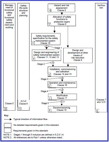
1. H&RA (Hazards and Risk Assessment)
The Hazards and Risk Assessment (H&RA) process identifies potential hazards and hazardous events associated with processes and equipment. It evaluates the sequence of events leading to hazardous incidents, assesses process risks, determines risk reduction needs, and identifies necessary safety functions for achieving the required risk reduction. This process relies on inputs such as process design, layout, manning arrangements, and safety targets, and produces outputs like descriptions of hazards, required safety functions, and associated risk reduction measures.
2. Allocation of Safety Functions to Protection Layers
Safety functions are then allocated to protection layers, with the Safety Integrity Level (SIL) defined for each Safety Instrumented Function (SIF). Using the descriptions of required SIFs and associated safety integrity needs, this step results in a detailed allocation of safety requirements.
3. SIS Safety Requirements Specification
The Safety Instrumented System (SIS) safety requirements are specified to ensure each SIS meets its intended functions and associated safety integrity. This involves defining requirements for both the SIS and its application programs, resulting in a comprehensive set of SIS safety and application program requirements.
4. SIS Design and Engineering
The design and engineering phase of the SIS ensures the system meets the SIF requirements and their associated safety integrity. Based on the specified safety requirements and application program safety needs, this phase produces the hardware and software designs and a plan for integration testing.
5. SIS Installation, Commissioning, and Validation
Installation, commissioning, and validation ensure the SIS is fully functional and compliant with safety requirements. By integrating and testing the SIS according to the design and validation plans, this phase confirms that all safety functions operate as intended, with results documented for integration tests, installation, and commissioning.
6. SIS Operation and Maintenance
During operation and maintenance, the SIS is monitored and maintained to preserve functional safety. Activities are guided by the SIS safety requirements, design specifications, and operational plans, ensuring that the system continues to perform as required.
7. SIS Modification
Modifications to the SIS involve making corrections, enhancements, or adaptations while maintaining the required SIL. These updates are implemented based on revised safety requirements, ensuring the system remains compliant and effective.
8. Decommissioning
Decommissioning processes ensure the safe and structured removal of Safety Instrumented Functions (SIFs) while maintaining proper safety measures. As-built safety requirements and process information guide this phase, leading to the controlled deactivation of SIFs.
9. SIS Verification
Verification activities evaluate outputs from each lifecycle phase, ensuring consistency and compliance with the initial inputs and established standards. A verification plan ensures thorough assessment, with results documented for each phase.
10. SIS FSA (Functional Safety Assessment)
The Functional Safety Assessment (FSA) provides an evaluation of the SIS’s achieved functional safety. Using the FSA plan and SIS safety requirements as references, this assessment results in a formal judgment on safety performance.
11. Safety Lifecycle Structure and Planning
Finally, the safety lifecycle structure and planning establish a comprehensive framework for executing all lifecycle steps. This phase results in a detailed safety plan to guide the entire process.
Advantages of Safety Lifecycle
- The safety lifecycle was created to help designers of safety instrumented systems build safer and more cost-effective systems.
- By analyzing the process risk, a system can be designed to enable that particular risk to be reduced to a tolerable level—not over-designed and not under-designed.
- The probabilistic verification included in the safety lifecycle helps engineers create “balanced” designs. Balanced designs put equal emphasis on all parts of the safety instrument function — logic solvers and field devices.
- The performance-based nature of the probabilistic SIL verification also allows designers the freedom to innovate, find better designs that meet safety integrity performance, and reduce lifecycle costs.
- Perhaps most important, the safety lifecycle concept as presented in international standards provides a common way to design throughout the world. No longer are there specific national standards with different details that change from country to country — at least for the process industries.
References:
- IEC-61511
- Functional Safety from Scratch by Peter Clarke
- Safety Integrity Level Selection by Edward M. Marszal, P.E., C.F.S.E., Dr. Eric W. Scharpf, MIPENZ
- Safety Instrumented Systems Verification: Practical Probabilistic Calculations, William M. Goble Harry Cheddie