A thermosyphon reboiler is important for distillation column, quietly powering the process that separates liquids into their pure components. These heat exchangers operate without the need for mechanical pumps, relying instead on natural circulation driven by fluid density differences. By heating liquid from the column’s base, it generates vapor that drives the separation, making it a go-to choice in industries like oil and gas, petrochemicals, and chemical processing. Its straightforward design, energy efficiency, and low maintenance make it a reliable option. This guide dives deep into their working principles, design considerations, and troubleshooting strategies, offering a complete understanding for professionals.
What Is a Thermosyphon Reboiler?
A thermosyphon reboiler is a heat exchanger that plays a key role in distillation columns, turning liquid into vapor to drive the separation of components based on their boiling points. Unlike other reboilers that rely on pumps to move fluid, this one uses natural circulation, driven by the difference in density between liquid and vapor. Think of it like a self-sustaining cycle where heat creates movement without any mechanical device. This simplicity makes thermosyphon reboilers a favorite in industries like oil and gas, petrochemicals, and chemical processing, where efficiency and reliability are important.
How Does a Thermosyphon Reboiler Work?
The beauty of a thermosyphon reboiler lies in its ability to harness natural forces to keep things moving. Here’s a simple breakdown of how it operates:
- Liquid Feed: Liquid from the bottom of a distillation column flows into the reboiler, usually through a pipe connected to the column’s sump, entering the tubes of a shell-and-tube heat exchanger.
- Heating Process: A hot medium, like steam or hot oil, flows through the shell side, transferring heat to the liquid inside the tubes. This heat causes some of the liquid to boil and form vapor bubbles.
- Natural Circulation: The vapor-liquid mixture is lighter than the incoming liquid because vapor is less dense. This creates a buoyancy effect, pushing the mixture upward through the tubes and back toward the column, while denser liquid flows in to take its place.
- Vapor Return: The vapor generated rises into the distillation column, driving the separation process by interacting with liquid on trays or packing, while the remaining liquid recirculates for further heating.
This self-regulating cycle, driven by density differences, eliminates the need for pumps, making the system energy-efficient and low-maintenance.
Vertical Thermosyphon Reboilers
Vertical thermosyphon reboilers are a popular choice due to their compact design and efficient circulation. In these systems, liquid enters vertical tubes at the bottom, is heated by shell-side steam, and exits as a vapor-liquid mixture at the top. Key features include:
- Enhanced Circulation: Gravity aids the natural flow, making vertical designs ideal for high-heat-transfer applications.
- Compact Footprint: Perfect for space-constrained plants.
- Maintenance: Pull-through floating head designs simplify tube cleaning, though they reduce tube count due to bolting needs.
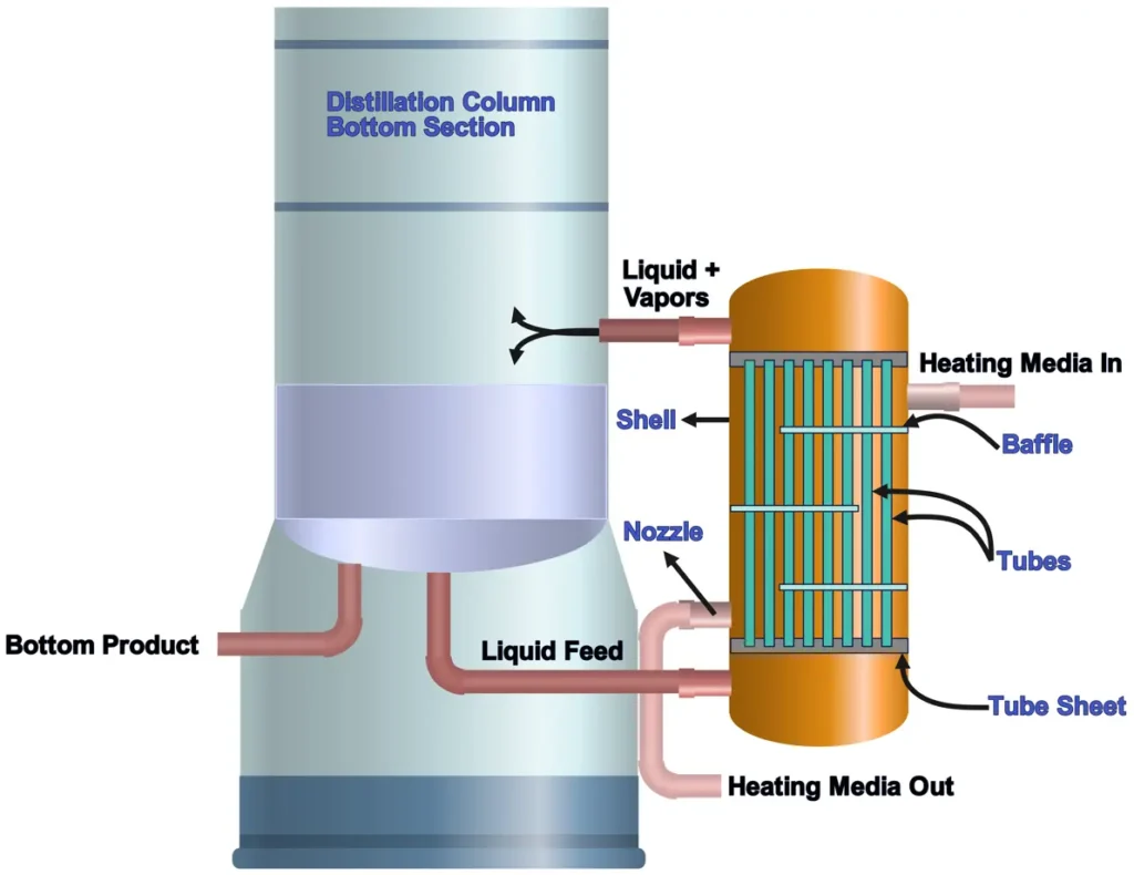
Key Components of Thermosyphon Reboiler
- Tubes: Typically, ¾ in. to 1 in. in diameter, arranged in a triangular or square pitch. Triangular layouts boost heat transfer by increasing turbulence, while square layouts are easier to clean for fouling-prone fluids.
- Shell: A steel casing (often 3/8 in. thick for pressures up to 300 psi) that houses the tube bundle and holds the heating medium.
- Baffles: These guide the shell-side fluid across the tubes, enhancing heat transfer. Segmental baffles with 20–25% cuts are common, spaced at 0.3–0.5 times the shell diameter.
- Tubesheet: A plate separating the shell and tube fluids, designed to handle thermal stress and corrosion.
- Nozzles: Sized to ensure smooth fluid entry and exit, minimizing pressure drop.
Design Steps for Thermosyphon Reboiler
- Define Heat Duty: Calculate the heat needed based on the flow rate and desired vaporization, like the 360,000 Btu/h required for processing 10,000 lb/day of a product with a boiling point of 276.5°C.
- Select Fluid Properties: Know the liquid’s density, viscosity, and thermal conductivity to predict flow and heat transfer behavior.
- Estimate Heat Transfer Coefficient (U): For steam heating aqueous solutions, U typically ranges from 1000–1500 W/m²°C; for heavy organics, it’s 600–900 W/m²°C.
- Calculate Heat Transfer Area: Use the equation Q = U A ΔT, where Q is the heat duty, A is the area, and ΔT is the temperature difference.
- Optimize Tube Layout: Use equations to estimate the number of tubes.
- Check Pressure Drop: Ensure tube-side and shell-side pressure drops (e.g., <10 psi) support natural circulation without excessive resistance.
Considerations
- Material Selection: Choose corrosion-resistant materials like stainless steel or titanium, especially for harsh process fluids.
- Fouling: Include fouling factors (e.g., 3000–5000 W/m²°C for aqueous solutions) to account for deposits that reduce heat transfer.
- Piping Layout: Minimize friction in inlet and outlet pipes to maintain smooth flow, as excessive resistance can disrupt circulation.
Role in Distillation Columns
In a distillation column, the thermosyphon reboiler is the powerhouse at the base, heating the liquid pool to generate vapor that rises through the column, separating components by their boiling points. Its performance effects:
- Product Purity: Consistent vapor flow maintains separation efficiency.
- Energy Use: Natural circulation cuts energy costs compared to pump-driven systems.
- Column Stability: Proper vaporization prevents issues like flooding or poor tray performance.
The reboiler’s integration with the column, via carefully designed piping and elevation, ensures a steady liquid head to drive circulation.
Circulation Rate Dynamics
The circulation rate in a thermosyphon reboiler hinges on the density difference between the incoming liquid and the outgoing vapor-liquid mixture. Key factors include:
- Liquid Head: The height difference between the column’s liquid level and the reboiler inlet drives flow. For instance, a 2,100-gallon still at 70% capacity provides adequate head.
- Heat Input: More heat increases vaporization, lowering the mixture’s density and boosting circulation. A vapor fraction of 10–30% is typical.
- Piping and Tube Design: Larger pipes and optimal tube sizes (e.g., ¾ in. diameter) reduce friction, while velocities of 3–8 ft/s in tubes prevent fouling without causing erosion.
- Baffle Spacing: Closer spacing (e.g., 7 in. for a 35 in. shell) increases turbulence but must balance pressure drop.
Engineers aim for a circulation ratio of 3:1 to 10:1 (liquid recirculated to vapor generated) to ensure stable operation without vapor locking, where excessive vapor blocks liquid flow.
Troubleshooting Thermosyphon Reboiler Issues
Here are common problems and solutions:
- Low Circulation:
- Cause: Insufficient liquid head, high viscosity, or pipe blockages.
- Solution: Verify the column’s liquid level, clear obstructions, or adjust piping to reduce friction.
- Fouling:
- Cause: Deposits on tube surfaces reducing heat transfer.
- Solution: Clean tubes mechanically or chemically, and maintain velocities above 3 ft/s to minimize buildup.
- Vapor Locking:
- Cause: Excessive vaporization halting liquid flow.
- Solution: Lower heat input or adjust reflux ratios.
- High Pressure Drop:
- Cause: Tight baffle spacing or small tube clearances.
- Solution: Increase baffle spacing or switch to a square pitch for lower resistance.
- Tube Leaks:
- Cause: Corrosion or poor tube-to-tubesheet joints.
- Solution: Use corrosion-resistant materials or double tubesheets for critical applications.
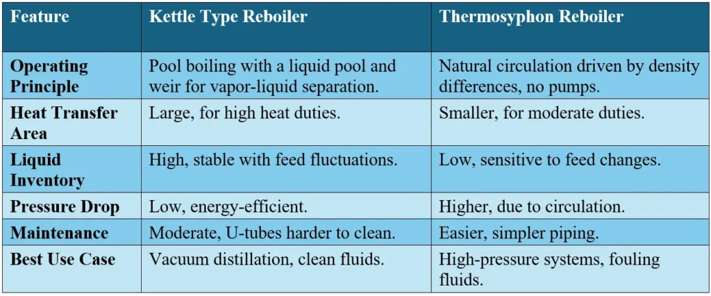
Difference between a Kettle Type Reboiler and a Thermosyphon Reboiler
The key features comparing Kettle Type Reboiler and Thermosyphon Reboiler is as follows:
Why Choose a Thermosyphon Reboiler
Thermosyphon reboilers shine because they:
- Save Energy: No pumps mean lower operating costs.
- Simplify Maintenance: Fewer moving parts reduce downtime.
- Ensure Reliability: Natural circulation is robust when designed correctly.
- Adapt to Needs: Suitable for a range of fluids, from water to heavy organics, if fouling and viscosity are managed.
People Also Asked Questions with Answers
Why are vertical thermosyphon reboilers preferred?
Vertical designs offer better circulation due to gravity, a smaller footprint, and easier integration with distillation columns, making them ideal for space-constrained, high-efficiency applications.
How can I improve circulation in a thermosyphon reboiler?
Ensure sufficient liquid head, optimize tube and pipe sizes for velocities of 3–8 ft/s, and adjust baffle spacing to minimize pressure drop while maintaining turbulence.
How does fouling affect a thermosyphon reboiler?
Fouling increases thermal resistance, reducing the heat transfer coefficient . This lowers the reboiler’s efficiency, potentially causing low circulation or uneven heating. Regular cleaning and monitoring are essential.
Are vertical thermosyphon reboilers better than horizontal ones?
Vertical thermosyphon reboilers often provide better circulation due to their orientation, but horizontal ones may be preferred for specific applications or easier maintenance. The choice depends on process requirements and space constraints.
References
- Thulukkanam, K. (2013). Heat Exchanger Design Handbook. CRC Press.
- Kister, H. Z. (1992). Distillation Design. McGraw-Hill Professional.
- Couper, J. R., Penney, W. R., Fair, J. R., & Walas, S. M. (2005). Chemical Process Equipment: Selection and Design. Gulf Professional Publishing.
- Kern, D. Q. (1950). Process Heat Transfer. McGraw-Hill Book Company, Inc.
- Sinnott, R. K., & Towler, G. (2008). Chemical Engineering Design: Principles, Practice and Economics of Plant and Process Design.
- https://chemicalengineeringworld.com
- https://www.sciencedirect.com