
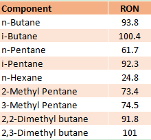
The Isomerization process in a petroleum refinery is the catalytic process that converts low octane number straight-chain hydrocarbon molecules (C4, C5, C6) into branched-chain hydrocarbons with the same carbon number and high octane number. The isomerization reaction rearranges the carbon skeleton of a molecule without adding or removing anything from the original material and transforms the normal paraffins into iso-paraffins. The table shows the difference in RON between normal and iso components.
The stringent environmental regulations worldwide have resulted in the increased demand for clean fuels, lead phaseout, minimization of benzene, and aromatics. This has increased the requirement of the Isomerization process in the oil refinery because it markedly helps to meet the low benzene high octane gasoline blend. More about gasoline fuel specifications can be seen in my previous blog ” Euro Specifications of Gasoline Fuel”
Objectives of Isomerization Process in Oil Refinery
The isomerization process in oil refining is critical in the current scenario of clean fuels and serves the following purposes ;
- Improves the RON of light naphtha gasoline from 65 to 92, depending upon the Isomerization unit configuration, catalyst type, and requirement of the refiner.
- Removes, benzene, and aromatics form the naphtha and make an ideal blending component for the gasoline pool.
- In the case of isomerization of Butane, it is used to prepare feed for the alkylation unit.
- Helps the oil refinery to manage the gasoline pool by providing high RON naphtha. Low-quality straight run C5~C6 gasoline is difficult to blend with other gasoline streams, therefore creating a bottleneck for the refinery operation.
Isomerization Catalysts
There are three types of isomerization catalysts being used in the industry but Pt /Chlorinated Alumina catalyst is widely used for the isomerization process of light naphtha.
- Pt (Platinum) and chlorinated alumina with high chlorine content, which is considered quite active. This is a dual-function catalyst consisting of highly chlorinated alumina (8–15 w% Cl2) which is responsible for the acidic function of the catalyst. Platinum is deposited (0.3–0.5 wt%) on the alumina and is responsible for the metal function of the catalyst.
- Pt/zeolite catalyst consists of Zeolites (Crystallized Silico Aluminates) that provide acid function while Pt impregnated on zeolites provides a metal function to the catalyst.
- Metal Sulfate Catalysts are new in the market are more active than Zeolite type catalysts and show resistance to poisonous contaminants. In addition, they can also be regenerated like Zeolite catalysts.
The basic difference in these catalysts is that Pt/Chlorinated catalysts are very sensitive to (water, CO, CO2, sulfur, Nitrogen) impurities and require pre-treatment of the feed while Pt/Zeolite and Metal Sulfate Catalysts can resist the impurities and therefore do not require feed pre-treatment. Further, Pt/Zeolite and Metal Sulfate Catalysts require gas recycling due to the high flow of hydrogen gas requirement.
Poisons for Pt (Platinum) and chlorinated alumina Catalyst
- Sulfur (H2S) is a temporary poison that can be removed from naphtha by an upstream hydrotreating unit and from the feed gas stream can be removed by a Sulfur guard bed reactor.
- Organic Nitrogen, Oxygenated compounds like water, CO, and CO2 are permanent poisons for the catalyst. Organic Nitrogen from the naphtha feed is removed in the hydrotreating unit while moisture from the feed gas stream is removed by dryers upstream of the isomerization reactors. Further, CO and CO2 present in the gas stream are removed by the Methanator reactor.
Isomerization Process Reactions Mechanism
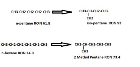
- The isomerization reactions are exothermic, and equilibrium limited, low temperature favors the isomerization reaction. However, operating at low temperatures will decrease the reaction rate. For this reason, a very active catalyst must be used. Isomerization of normal-pentane and normal hexane is shown below;
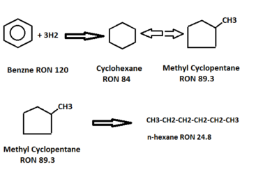
- Benzene is hydrogenated to cyclohexane, which is then isomerized to an equilibrium mixture of methyl cyclopentane, cyclohexane, and partially converted to isoparaffin. This represents an octane loss but liquid volume increases. Benzene saturation reactions are highly exothermic, so its concentration should not be increased above the design limits to control reactor temperatures.
- Side reactions like Hydrocracking can also proceed along with normal isomerization reactions. These side reactions can be controlled by the optimum reaction temperature, low concentration of C7 plus, and cyclic components. A higher concentration of C7 plus and cyclics will affect the isomerization reactions.
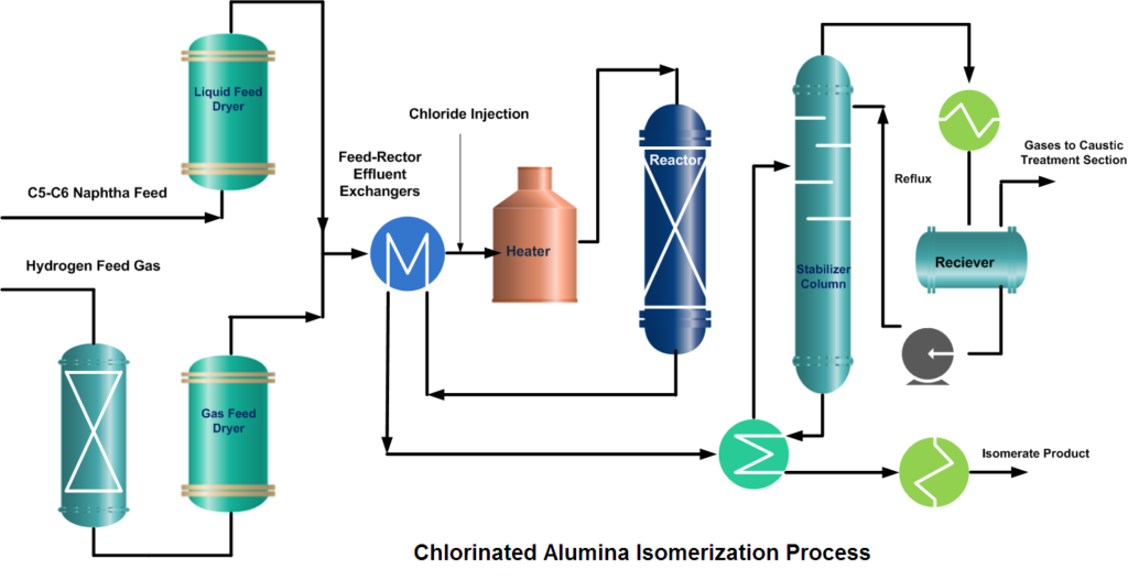
Isomerization Unit Process Description
The isomerization process is designed for continuous catalytic isomerization of pentanes, hexanes, and their mixtures. The isomerization reactions proceed in the presence of hydrogen over a fixed bed of a catalyst and at operating conditions that promote isomerization and minimize hydrocracking.
In a typical isomerization unit, light naphtha is first hydrotreated and then dried to remove any moisture content. Similarly, from the hydrogen gas stream, H2S is removed in the guard bed reactor and Oxygenates (CO, CO2) are converted to water (H2O) and methane (CH4) in a Methanator reactor. Afterward, hydrogen gas is dried and mixed with naphtha feed. A small amount of organic chloride is injected into the combined feed stream and then heated to the reaction temperature.
After mixing the dry and treated feed and gas streams, the combined feed is preheated by the reactor effluent and then finally heated in a heater up to the required reaction temperature. Process requirement determines whether one or more reactors are to be used. In two-reactor units, the feed flows in the first reactor, which operates at high temperature and high reaction rates, to convert benzene and some heavies. While the second reactor operates at low temperature thus favors the equilibrium shifting to complete the isomerization reactions.
If Pt/Zeolite or metal sulfate catalysts are used then the configuration of the unit consists of a recycle gas system. The reactor effluent flows to a product separator, where hydrogen is separated from the other reaction products. Recovered hydrogen can go to a recycle compressor, which returns it to the reactors, or it can be treated and sent to the fuel gas system.
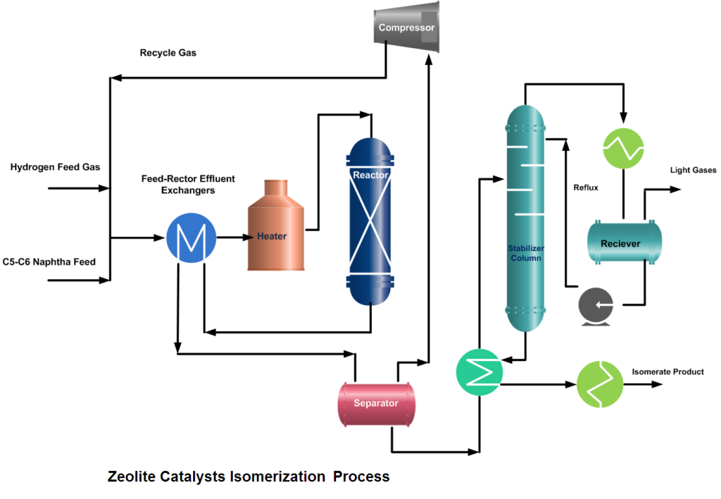
But if Pt (Platinum) and chlorinated alumina catalyst is used which does not require, recycle gas then after cooling, the reactor product will go to a stabilizer column, which removes light hydrocarbon gases (C1~C4), HCl, and remaining dissolved hydrogen. The stripped gases are treated with caustic in a scrubber. The stabilized liquid goes to storage or gasoline blending.
RON of the Isomerate can be improved up to ~ 92 by recycling normal pentane and normal hexane from the isomerization product. To accomplish this de-isopentane and de-isohexane equipment have to install.
For further discussion, and queries please comment in the box below or contact at admin@

Certified Functional Safety Professional (FSP, TÜV SÜD Germany), Certified HAZOP & PHA Facilitator, LOPA Practitioner, QRA/FERA and Specialist in SIL Verification & Functional Safety Lifecycle, with 18 years of professional experience in Plant Process Safety across Petroleum Refining and Fertilizer Complexes.


3 thoughts on “Isomerization Process in Petroleum Oil Refinery”
AOA, very informative and new topic for me