Understanding Architectural Constraints in Functional Safety
In the world of functional safety, ensuring that systems operate reliably under all circumstances is paramount. One key concept in achieving this reliability is architectural constraints. These are limitations placed on hardware used to implement safety-instrumented functions (SIFs). These constraints ensure that safety integrity levels (SILs) are achievable and maintainable, irrespective of the subsystem’s performance calculations. Let’s explore the concept of architectural constraints and how they shape safety system designs. The Architectural Constraints for each device is listed on its certification.
What Are Architectural Constraints?
Architectural constraints are defined by the hardware’s design, component type, and redundancy requirements. The constraints are necessary to prevent exaggerated risk reduction claims from a single subsystem. For example, no single set of equipment can claim to reduce risk by seven orders of magnitude. Standards like IEC 61508 and IEC 61511 outline tables and requirements that enforce mandatory redundancy to achieve higher SIL ratings.
Devices used in SIFs are categorized into Type A and Type B components, based on complexity:
- Type A components: Simple devices with well-defined failure modes (e.g., relays, valves, actuators, Solenoids, pneumatic boosters, Simple electronic modules (resistors, capacitors, op-amps).
- Type B components: Complex devices incorporating microprocessors or other advanced technologies, with less historical reliability data. Due to their design complexity and rapid technological advancements, they lack the long operational history needed to fully understand failure modes. Examples include Devices with new-generation microprocessors, Advanced ASICs, Other cutting-edge technologies.
Hardware Fault Tolerance (HFT)
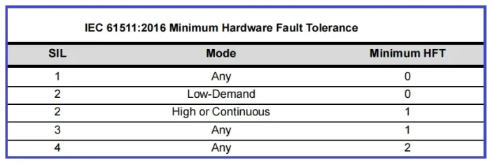
IEC 61511:2016 specifies minimum hardware fault tolerance levels based on the desired SIL rating. HFT is the number of dangerous failures a system can tolerate before losing its ability to perform the safety function. HFT is the ability of a subsystem to achieve the design intent of the SIF, even in the presence of hardware faults. HFT is achieved by providing redundant equipment for example, two sensors in a 1oo2 architecture.
Each subsystem initiators, logic solver and final element required to have a particular level of HFT. For example, if HFT of 1 is specified, the subsystem must not fail dangerously in the presence of any one element having a hardware fault (random failure).
The example just mentioned, two sensors in a 1oo2 architecture, has a HFT of 1.
The required HFT depends on the target SIL of the SIF, and also on which standard is being applied: IEC 61508 and IEC 61511. For higher SIL levels, systems must include redundant components to ensure functionality even in the event of partial failures.

Purpose of Hardware Fault Tolerance (HFT)
- The purpose of providing an HFT requirement is to prevent over-reliance on low random hardware failure probability to achieve a high SIL. If there were no HFT requirement, a user could claim that a simple 1oo1 SIF can theoretically achieve a very high SIL by intensive testing (or by applying unreasonably low Lambda (DU) or unfeasibly high proof test.
- The HFT requirement also provides greater safety assurance in high demand and continuous mode functions, where faults may lead to accidents before they can be discovered by proof testing.
IEC 61508: Two Routes for Hardware Safety Integrity
IEC 61508 provides two approaches to achieving hardware safety integrity:
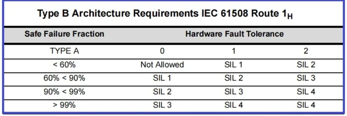
- Route 1H (Hardware Fault Tolerance and Safe Failure Fraction): Focuses on calculating the Safe Failure Fraction (SFF) to determine the system’s ability to handle failures.


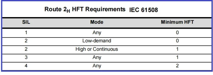
- Route 2H (Component Reliability and Operational Data): Relies on detailed operational data, historical reliability, and increased confidence in component performance.
The “H” subscript indicates these routes apply to hardware safety integrity, distinct from routes related to systematic safety integrity (Routes 1S, 2S, 3S).

Why Are Architectural Constraints Important?
Architectural constraints ensure that safety systems are designed with adequate redundancy and fault tolerance. They help avoid over-reliance on a single device or subsystem, especially for high-risk applications. For example:
- A higher SIL rating may require dual redundancy (e.g., two valves working in parallel) to tolerate a single dangerous failure.
- By classifying components into Type A or B, engineers can account for differences in reliability and historical data.
References:
- IEC-61511 /IEC-61508
- Functional Safety from Scratch by Peter Clarke
- Safety Instrumented Systems Verification: Practical Probabilistic Calculations by William M. Goble Harry Cheddie


